Camera calibration answers a concrete question. Which parameters explain why a point in 3D appeared at this particular pixel? Separating camera intrinsics, pose, and lens distortion helps avoid the same frame mix-ups in pose estimation, SLAM, and human height estimation.
#Four coordinate systems
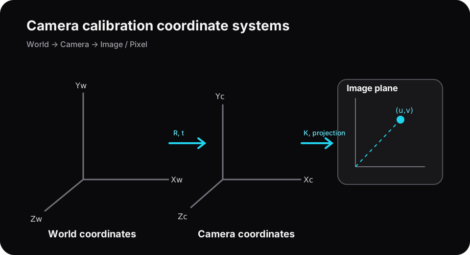
- World
Pw=[Xw,Yw,Zw,1]ᵀgives the object and camera a common frame of reference. - Camera
Pc=[Xc,Yc,Zc]ᵀplaces the origin at the optical center. - Normalized image
[x,y]=[Xc/Zc,Yc/Zc]gives the projection before applying focal length and pixel units. - Pixel
[u,v]gives the image coordinates read from the sensor.
The basic equation takes a world point to a pixel.
s [u, v, 1]ᵀ = K [R | t] [Xw, Yw, Zw, 1]ᵀ[R|t] is the rigid transform from world to camera coordinates. K maps the normalized image to pixels. A rigid transform consists of rotation and translation and preserves scale. Allowing a uniform change in scale gives a similarity transform.
#Extrinsics and the camera’s viewing direction
Pc = R Pw + tHere R is a 3×3 rotation matrix and t a 3×1 translation vector. Reading t as the camera position in world coordinates can lead to a sign error. If the camera center in world coordinates is C, then t=-RC. Check which direction a library function uses for its transform.
#Intrinsics and how a ray maps to a pixel
K = [ fx  s  cx
       0 fy  cy
       0  0   1 ]
fx, fyare the focal lengths in pixels.cx, cy: principal pointsis the axis skew, usually set to zero for modern cameras.
Even at a fixed field of view, changing resolution changes fx, fy, cx, and cy in pixel units. If the inference image is resized from the calibration resolution, scale the corresponding entries of K along each axis.
#Distortion in a real lens
The standard OpenCV pinhole model uses radial coefficients k1,k2,k3... and tangential coefficients p1,p2. A fisheye camera may need a different model. Extra coefficients can improve fit on the calibration images while overfitting the sampled field of view. Save the model and flags with the results.
#Calibration procedure
- Prepare a checkerboard or ChArUco board of known dimensions.
- Capture the board at different distances and tilts, including views near the edges of the image.
- Locate the corners with subpixel precision.
- Use the object and image points to optimize
K, distortion, and each view’sR,t. - Check undistortion and reprojection error on images held out from calibration.
ok, K, dist, rvecs, tvecs = cv2.calibrateCamera(
    object_points,
    image_points,
    image_size,
    None,
    None,
)

projected, _ = cv2.projectPoints(
    object_points[0], rvecs[0], tvecs[0], K, dist
)#Where mean reprojection error falls short
A small mean can hide large errors at a particular corner, distance, or camera orientation. Check the following as well.
- The per-image RMS and distribution of errors across all points
- A map of residual vectors by image position
- Performance beyond the intended working distance
- Coverage of different board orientations and positions
- Any changes in focus or zoom since calibration
For height estimation, calculate how many centimeters a 0.2-pixel difference represents at each working distance. In SLAM, even a small calibration bias can accumulate along a long trajectory.
#Experimental details to save
- Camera and lens models, resolution, focus, and zoom
- Board geometry and the unit used for square length
- OpenCV version and calibration flags
K, distortion coefficients, image size- Reprojection error per image and image exclusion criteria
- Axis directions and transform conventions