#1. A coordinated design rather than a more complicated wing
NPU-Sparrow expands the performance range of a flapping-wing robot by coordinating changes in tail area with wing-incidence control, rather than adding many independently articulated wing segments. The paper reports level-flight speeds of 4.5–13.2 m/s, a peak roll rate of 375°/s, a 20.4% reduction in steady-turn radius, and demonstrations of loops and barrel rolls. Linking an aerodynamic model to wind-tunnel measurements and outdoor flight is a major strength.[1]
The Nature Communications publication of 24 September 2026 is a peer-reviewed, accepted early version. Its contribution is that coordinated morphology and control can expand the accessible flight-performance space with relatively few degrees of freedom. It does not establish complete long-range mission autonomy, reliability in severe gusts, or validated payload and endurance performance across conditions.[1]
#2. Why efficient cruising and agile maneuvering conflict
Efficient travel requires reducing unnecessary drag and power consumption. Rapid maneuvers and slow flight require sufficient lift and control moments. A larger tail can provide control authority but can also add aerodynamic and structural burdens. On a small aircraft, the mass and power of an additional actuator can materially change the system, so independently reproducing every biological movement is not necessarily beneficial.[1]
Flapping-wing systems add another coupling: passive deformation of a flexible wing contributes to lift and thrust. Structural changes intended to add a degree of freedom can disrupt useful elastic deformation and inertia distributions. Matching a bird’s joint count is therefore less important than identifying controllable engineering variables that generate the required forces and moments.[1]
One way to make an aircraft capable of both cruising and rapid maneuvering is not to maximize everything at one fixed configuration, but to move between favorable operating points. Tail tucking and extension, combined with wing-angle control, provide that ability here. The efficiency–maneuverability trade-off is not abolished. The range of choices available within it is expanded.
#3. What actually moves on the 90-gram robot
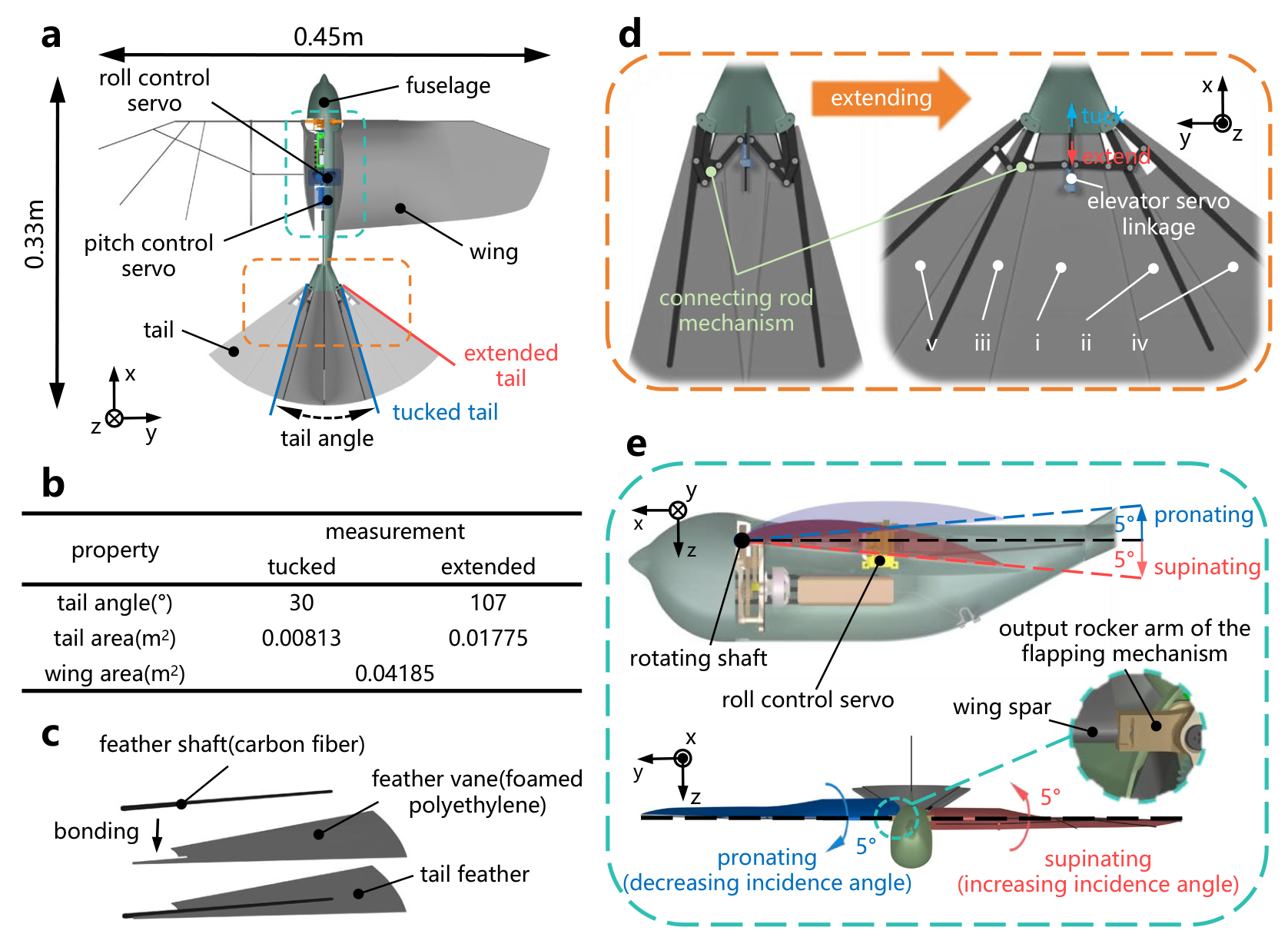
The design uses a takeoff mass of approximately 90 g, a 0.45 m wingspan, and a reference cruise speed of 7 m/s. The paper describes an 8 Hz reference flapping frequency and up to 16 Hz under maneuvering conditions. These are parameters of the investigated design, not universal optima or scaling laws for aircraft of another size.[1]
In the first original illustration, Figure 2, panel a shows the vehicle, panel b its geometry, panel c the artificial tail feathers, panel d the linkage that folds and extends them, and panel e the wing-incidence mechanism. The linkage coordinates the feather arrangement rather than assigning many independent joints to the tail. Left and right wing incidence is also controlled. Thus, low degree of freedom does not mean passive flight, no control, or that the entire robot contains only two motors.[1]
The supplement distinguishes mean wing incidence, used for pitch and lift modulation, from differential incidence, used for roll control. It explicitly excludes differential roll incidence from the cycle-averaged longitudinal model. Correctly predicting longitudinal trends is consequently not equivalent to predicting rapid roll and every unsteady maneuver with the same accuracy.[2]
#4. The 13-degree condition is not a tail-angle command
Installation angle describes how a surface is mounted relative to the vehicle. Angle of attack concerns the surface’s orientation relative to airflow. Vehicle angle of attack, wing incidence, tail installation angle and the wing-induced flow all contribute to the effective aerodynamic angle at each surface. “Rotate the tail to 13 degrees to change mode” is not what the paper’s variable definitions say.[1][2]
The following relationships summarize the supplementary definitions. Alpha is the complete vehicle’s angle of attack relative to the freestream, i denotes installation angle, and epsilon represents the induced flow angle at the tail. The wing and tail do not necessarily experience the same effective angle of attack even at one vehicle attitude.
At lower angles of attack, the selected negative-installation-angle tail supplies negative lift and the pitching moment required for longitudinal static stability. As vehicle angle of attack increases, its effective incidence and lift direction can change, allowing it to act as an auxiliary lifting surface. The reported role change above 13 degrees belongs to the tested vehicle and control conditions. It is not a universal transition angle for birds or aerial robots.[1]
The selected tail installation angle of −10 degrees is a practical design point. That −10-degree installation angle and the 13-degree vehicle angle of attack are different variables. The supplement treats −10 degrees as a configuration combining stability margin with maneuvering capability, rather than a unique mathematical optimum. Coordinate frames and definitions matter more for reproduction than memorizing an isolated angle.[2]
#5. What wind-tunnel validation establishes—and where the model differs
The authors constructed a predictive model using wing–body and tail responses, then tested its trends with complete-vehicle wind-tunnel measurements. They compared positive- and negative-lift tail configurations, tail-area modulation alone, and strategies that coupled it with wing incidence. The relevant question is not simply which shape produces the most force, but which strategy expands useful combinations of stability, force and moment while satisfying flight conditions.[1]
Extending the tail changes the aerodynamic center and pitching moment. Coordinating wing incidence in one direction can amplify that effect, while another direction can suppress it. The correct interpretation is therefore not “a larger tail is always better.” Cruise advantages of a tucked tail and maneuvering capability of an extended tail must be selected appropriately. A morphing mechanism needs a suitable coordination rule, not just the ability to move.[1]
The quantitative model discrepancy is disclosed. Supplementary Note 2 explains that the model captures the direction and relative ordering of aerodynamic-center migration but overpredicts its magnitude compared with wind-tunnel measurements. The authors reduced the incremental sensitivity associated with tail-area changes to test the robustness of their design conclusions. Broad trends persisted, while the static-stability boundary and exact optimum installation angle were more sensitive.[2]
This is information about where to trust the model, not evidence of a perfect model. Agreement in direction can inform design intuition. It does not establish safety near the predicted stability boundary or justify transferring fitted coefficients directly to an aircraft of different size. Static stability is also not the same as dynamic stability, gust rejection, or every margin of the closed-loop controller.
#6. Four outdoor-flight results that must not be conflated
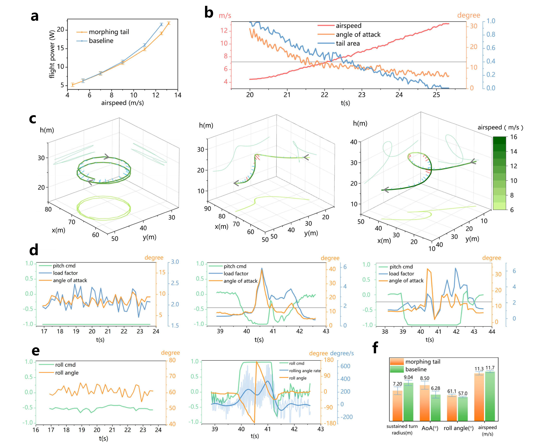
The second original illustration, Figure 6, combines flight power and speed, tail-state changes, turn/loop/barrel-roll trajectories, and control inputs alongside attitude and load-factor responses. Different tests and axes appear within one figure. Their numbers should not be extracted and combined into a single general performance claim. In particular, peak roll rate and steady-turn radius describe different motions.[1]
| Reported measure | Result | What it does not establish |
|---|---|---|
| Level-flight speed range | 4.5–13.2 m/s | A guaranteed envelope at every payload or wind condition |
| Peak roll rate | 375°/s | Sustained turning at that rate or the average roll rate |
| Steady-turn radius | 20.4% below the reference configuration | A matching improvement in energy use or mission duration |
| Demonstrated maneuvers | Loops and barrel rolls | Autonomous obstacle avoidance or long-term reliability certification |
Roll is rotation about the vehicle’s fore–aft axis; a turn curves its trajectory and changes its direction of travel. An aircraft may roll quickly yet lack the lift, speed or control margin needed to sustain the desired turn curvature. The 375°/s peak demonstrates roll-control authority, not a universal measure of all flight capabilities.
The turn-radius reduction is relative to the reference configuration defined in the study. Comparing it with another robot’s record requires compatible speeds, masses, load conditions and turn definitions. Demonstrating loops and barrel rolls adds evidence beyond a wind-tunnel-only study, but demonstrated maneuvers and success probabilities in arbitrary environments remain different propositions.[1]
#7. What a basic turn-radius equation tells us
In a simplified level, coordinated turn, speed and load factor determine the radius. The equation below follows a basic force balance; it does not reproduce the instantaneous flapping forces or the complete dynamics of outdoor maneuvers. Here n is lift divided by weight, and this relationship requires n greater than one.
At a fixed speed, a higher available load factor can permit a smaller turn radius. But radius also depends on the square of speed. A 20.4% reduction in radius therefore cannot be inverted into a claim that lift increased by 20.4%. Comparing actual maneuvers requires speed, load factor, attitude and control histories. This is why connecting flight records with wind-tunnel results matters.[1]
The elementary equation also exposes a design boundary. Reducing turn radius can increase the required load and structural or control burden. Wing–tail coordination can help satisfy those conditions, but it does not eliminate force balance. Adding a heavy sensor or battery changes mass, inertia and center of gravity, so identical settings cannot be assumed to produce identical maneuvers.
#8. What remains between this aircraft and an autonomous mission
This is research on aerodynamic design and vehicle control, not validation of a complete long-range autonomous mission. Goal planning, obstacle perception, localization, communications-loss behavior and safe landing are separate capabilities. Adding a vision or language model introduces payload, power and latency, so the maneuverability of the aircraft must be distinguished from the performance of the integrated autonomous system.
Important further questions include stability margins in gusts, wear or backlash after repeated actuator cycles, elastic changes, and performance as battery voltage changes during a longer flight. Few degrees of freedom may simplify a mechanism, but that alone does not prove a lower failure rate. Reliability must be demonstrated through repeated and environmental testing rather than inferred from component count.
Data availability is also the beginning of reproduction, not its completion. The publisher provides supplementary information, Source Data and flight-video links. Reproducing physical performance additionally requires compatible units, coordinate frames, wing deformation, actuator response and center of gravity. The supplementary coefficients specify square millimetres for area, degrees for angles, and particular force/moment units. Treating every coefficient as if it used SI base units would produce a different calculation.[2]
The authors declare no competing interests. This informs the context but does not substitute for generalization evidence or independent replication. This explainer likewise distinguishes checking the original figures and variable definitions from building and independently testing the aircraft.[1]
#9. The next validation milestones and the reusable idea
A useful follow-up would repeat comparisons that separate tail-area and wing-incidence effects under matched wing, mass and supply conditions. It should show which coordination rules help at which speeds and angles of attack—and where control reversal or reduced margins appear. Reporting variation and unsuccessful maneuvers alongside averages would make the design envelope clearer.
The next extensions are different wind conditions, payloads, battery states and longer flights. Researchers should also examine whether the controller remains stable when the aerodynamic model is imperfect, and whether model error can shift a design across the actual static-stability boundary. Claims about mission autonomy would need additional testing after perception and planning are placed inside the closed loop.
The most reusable lesson is not “replicate every avian movement,” but identify aerodynamic variables that alter performance and coordinate them through a small number of controlled degrees of freedom. The study connects the tail’s stabilizing and lifting roles through modeling, wind-tunnel measurements and real flight. Its speed envelope and maneuver records support that design logic; they do not yet describe a finished autonomous aircraft for every environment.[1][2]
#Sources and access scope
[1] Cao, Song, Chen and Ma, Wing-tail coordination balances efficient cruising and maneuvering flight in an avian-inspired flapping robot, Nature Communications, published 24 September 2026, DOI 10.1038/s41467-026-78005-x. Original source.
[2] Supplementary Notes to the same paper: aerodynamic variables and coefficients, quantitative aerodynamic-center discrepancy and design-sensitivity analysis. Original source.
[3] Transparent Peer Review file: assessment and responses concerning experiments, modeling and maneuverability. Original source.
Checked on 25 September 2026 against the publisher’s accepted early-version PDF, Figures 2 and 6, and Supplementary Notes 1 and 2. The publisher provides Source Data and flight-video links, but no independent refitting of the source data or full reanalysis of the videos was performed here. No physical reconstruction or flight replication was attempted. Original figures retain all panels and colors, with attribution and CC BY-NC-ND 4.0 notices; this explainer does not display advertising.